How to Switch Polarity on a Multi-process Welder
How to switch polarity on a multi-process welder between DCEP and DCEN for MIG, flux core, and stick welding using internal wire drive studs or front panel Dinse plugs.
 By WeldGearLab Editorial
Updated October 10, 2026
By WeldGearLab Editorial
Updated October 10, 2026
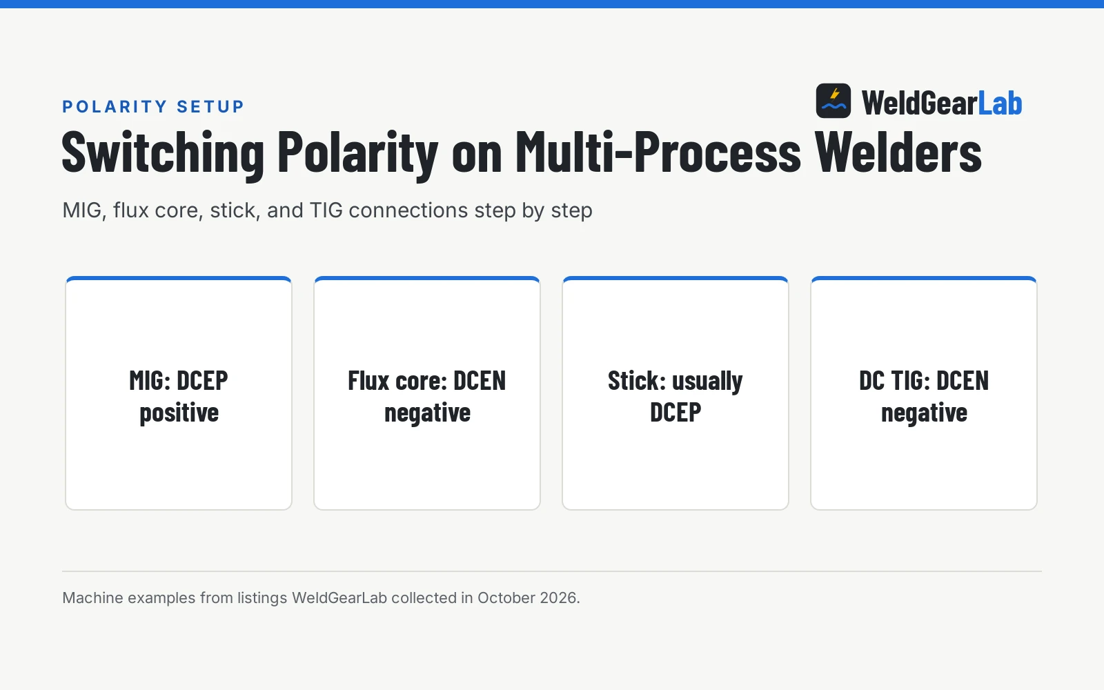
Learning how to switch polarity on a multi-process welder comes down to changing which terminal powers your welding gun and which terminal connects to your workpiece. On multi-process machines, solid-wire MIG welding requires direct current electrode positive (DCEP), where the wire gun connects to positive and the work clamp connects to negative. Gasless flux-cored welding reverses that arrangement to direct current electrode negative (DCEN), placing the gun on negative and the work clamp on positive. Switching between these modes requires opening the wire feed compartment or moving front panel cable plugs, securing the lugs tightly, and verifying your wire and gas settings before striking an arc.
As an Amazon Associate I earn from qualifying purchases. This guide links to our product roundups, where WeldGearLab earns a commission when you buy through links, at no extra cost to you. Read our affiliate disclosure.
Polarity rules in one paragraph
Direct current (DC) welding relies on electrical current flowing in one direction between positive and negative terminals. Polarity defines whether your welding torch or electrode connects to the positive terminal (DCEP) or the negative terminal (DCEN). In solid-wire MIG welding, DCEP is standard because it delivers smooth wire transfer, stable arc control, and cathodic cleaning action that breaks up surface oxides on the plate. In contrast, common gasless flux-cored wire requires DCEN to coordinate the melting rate of the outer steel sheath with the vaporization of internal fluxing agents, shielding the puddle and preventing porosity. For DC TIG welding on carbon and stainless steel, DCEN directs arc heat into the workpiece while protecting the sharp tungsten electrode from melting.
Side by side polarity comparison
| Welding Process | Polarity Designation | Torch or Gun Lead | Work Ground Clamp | Shielding Source |
|---|---|---|---|---|
| Gas MIG (solid wire) | DCEP (Electrode Positive) | Positive terminal (+) | Negative terminal (-) | External shielding gas |
| Flux-cored MIG (gasless) | DCEN (Electrode Negative) | Negative terminal (-) | Positive terminal (+) | Internal wire flux core |
| Stick welding (MMA) | DCEP (Electrode Positive) | Positive terminal (+) | Negative terminal (-) | Electrode flux coating |
| DC TIG (steel/stainless) | DCEN (Electrode Negative) | Negative terminal (-) | Positive terminal (+) | External pure argon gas |
Polarity requirements depend on consumable chemistry and process design rather than personal preference. Always inspect the manufacturer label on your wire spool or stick electrode package before connecting your leads, because running any wire on reversed polarity compromises weld strength and arc stability.
When DCEP electrode positive is the correct choice
Direct current electrode positive, also called reverse polarity, is the standard configuration for several common workshop processes:
- Solid wire gas MIG welding. Carbon steel, low-alloy steel, and stainless steel solid wires require DCEP with an external shielding gas mix. Positive polarity melts the wire smoothly and produces clean, flat beads with minimal spatter.
- MIG welding aluminum with a spool gun. Aluminum wire requires DCEP combined with pure argon shielding gas to strip oxide layers and ensure sound fusion.
- Common stick welding electrodes. Standard structural and maintenance electrodes produce their best arc characteristics and deepest penetration on positive electrode polarity.
When outfitting a home workshop or farm repair truck, reviewing our guide to the best multi-process welder options helps identify machines with straightforward polarity changeover systems and durable front panel connections.
When DCEN electrode negative is the correct choice
Direct current electrode negative, traditionally referred to as straight polarity, connects the torch to the negative terminal and the work clamp to positive. Use DCEN in the following situations:
- Gasless flux-cored wire welding. Self-shielded flux core wires feature internal flux agents that vaporize to shield the arc. Connecting the gun to negative controls wire melting speed and prevents excess porosity on structural joints.
- DC TIG welding on carbon and stainless steel. Placing the TIG torch on the negative terminal preserves the sharpened tungsten point and directs arc energy into the base metal.
- Specialty thin-gauge sheet metal stick rods. Certain thin-metal stick procedures use electrode negative to produce faster rod melt-off and shallower base metal penetration, helping avoid burn-through on thin sheet stock.
Our detailed guide on what polarity for flux core welding provides additional background on gasless wire metallurgy and joint preparation.
How to switch polarity on a multi-process welder
Changing your process on a multi-process machine takes only a few minutes when following an orderly sequence. Here is the step-by-step procedure to change polarity MIG to flux core or reconfigure your welding leads:
- Disconnect input electrical power. Switch off the machine power switch and remove the power plug from the wall receptacle or generator power source. Allow internal circuitry to discharge completely before opening cabinet panels.
- Open the wire feed cabinet door. Swing open the side access compartment to view the wire drive assembly. On most compact multi-process units, you will find two heavy threaded terminal studs marked positive (+) and negative (-), connected by a short, flexible power lead leading to the MIG gun receptacle.
- Loosen the terminal retaining hardware. Multi-process units use threaded thumb screws, knurled knobs, or hex nuts on the internal polarity terminals. Loosen the fastener securing the wire drive jumper lead.
- Reposition the wire drive power lead. For solid-wire MIG welding, secure the drive lead lug to the positive (+) stud. To change polarity MIG to flux core, lift the drive lead lug and attach it to the negative (-) stud. Tighten the retaining hardware firmly so the copper terminal makes solid electrical contact.
- Reposition the work ground clamp lead. Locate the front panel Dinse twist-lock sockets. When running solid-wire MIG (DCEP), insert the ground clamp plug into the negative (-) socket and twist clockwise to lock. When switching to flux core (DCEN), plug the ground clamp into the positive (+) socket and lock it firmly.
- Check wire drive rolls and shielding gas. If you changed polarity to run flux core wire, switch your drive roll to a knurled groove so the serrations grip the soft tubular wire without crushing it, and close the shielding gas cylinder valve. If you changed polarity to run solid wire MIG, verify your smooth V-groove roll is installed and open your gas regulator.
Before laying down a critical seam, strike a quick arc on clean scrap metal to confirm that the arc hums smoothly and the wire feeds without hesitation.
Internal terminal studs versus front panel connections
Welder manufacturers implement polarity switching through internal studs, external front panel receptacles, or automated internal switching.
Many compact wire feed units place polarity changeover studs inside the wire spool bay. A short jumper cable extends from the MIG drive assembly and attaches to either a positive or negative stud using a hand-tightened wing knob, while the work ground clamp plugs into a front panel socket. Forney, for example, includes an 8 foot ground clamp, an 8 foot electrode holder, and a 10 foot MIG gun with its 140 MP unit, which operates on 120-volt power. BILT HARD lists wire sizes of .023, .030, .035, .040, and .045 inch for its 250A multi-process machine, with a 60% duty cycle at 250A. On these cabinet-style machines, keeping internal studs free of metal grinding dust prevents electrical arcing across internal posts.
Other multi-process machines route manual connections directly through external front panel sockets. ARCPEX includes 10FT ground clamp and 10FT electrode-holder cables with its 200A dual-voltage machine. Both the torch lead and ground clamp plug into standard brass twist-lock Dinse receptacles on the faceplate. Lincoln Electric lists a 51 lbs weight on its POWER MIG 220 dual-voltage machine, which runs on 120V and 230V inputs. On these manual setups, swapping polarity requires simply unplugging each Dinse connector, inserting it into the opposite faceplate receptacle, and twisting a quarter turn clockwise to seat the copper lugs.
Select advanced units eliminate manual lead swapping between processes altogether. Miller highlights its QuickTech system on the 56-lb Multimatic 220, which operates on 120V and 240V power and welds mild steel up to 3/8 in, automatically determining polarity when switching between MIG and TIG processes without requiring manual cable adjustments.
Browsing our comprehensive multi-process welders hub helps compare cabinet layouts, wire drive designs, and portability across different machine classes.
Switching polarity for stick and TIG processes
Multi-process welders also support stick and TIG welding, which rely on their own specific cable arrangements:
- Stick welding (SMAW) lead setup. Most stick welding applications run on DCEP. Plug the electrode holder cable into the positive (+) front Dinse socket, and plug the work ground clamp into the negative (-) socket. If you encounter specific rods calling for DCEN, reverse those connections at the front panel.
- DC TIG (GTAW) torch setup. Connect the TIG torch power cable to the negative (-) front receptacle, and connect the work ground clamp to the positive (+) receptacle. Connecting a TIG torch to positive would melt the tungsten point immediately. Connect your argon gas line directly to your flowmeter or machine solenoid as indicated in your manual. When welding aluminum on AC-capable multi-process welders, the machine uses alternating current rather than direct current.
Our article on DC vs AC stick welding covers rod selection and arc behavior, while our guide on whether you can MIG weld without gas explains how gasless wire chemistries perform under field conditions.
Electrical safety and terminal maintenance. Always disconnect the power supply before touching internal terminal studs or changing cable connections. Inspect terminal nuts and Dinse plugs regularly for loose fits, copper oxidation, or heat discoloration, because poor contact causes resistance, voltage drops, and melted plastic housings. Keep your welding workspace dry, inspect cables for cracked insulation, and review our welding safety gear checklist for beginners to protect against electric shock, arc rays, and respiratory hazards.
Frequently Asked Questions
What happens if you weld with the wrong polarity on a multi-process machine?
Welding with reversed polarity causes excessive spatter, poor arc stability, and weak penetration. Running solid wire on electrode negative produces an erratic arc and heavy spatter, while running flux-cored wire on electrode positive overheats the wire and leaves porous, brittle beads. Checking your lead connections before striking an arc prevents contaminated welds.
Do you switch polarity inside the cabinet or on the front panel?
It depends on your welder design. Many multi-process machines route the wire drive power through an internal jumper lead inside the wire cabinet that connects to positive or negative studs, while the ground clamp plugs into the front panel. Other units place all manual polarity connections directly on the front panel using twist-lock Dinse receptacles, and some advanced models switch polarity automatically.
How do you change polarity from MIG to flux core?
To change polarity MIG to flux core on a typical manual machine, move your wire drive power lead from the positive terminal to the negative terminal. Then move your work ground clamp cable to the positive Dinse receptacle on the front panel. You must also turn off your shielding gas cylinder and install the proper drive roll for flux-cored wire.
What polarity is used for stick welding on a multi-process welder?
Most common stick electrodes run on DCEP, which places the electrode holder on the positive terminal and the work clamp on the negative terminal. Certain specialty rods call for DCEN to reduce penetration on thin sheet metal, or alternating current depending on coating chemistry. Always check the electrode packaging or maker recommendations before setting up your stick welding leads.
What polarity does DC TIG use on a multi-process machine?
DC TIG welding on carbon steel and stainless steel always uses DCEN, connecting the TIG torch to the negative terminal and the work clamp to the positive terminal. Running a TIG torch on positive directs excessive heat into the tungsten electrode, melting the tip and contaminating the weld pool. The negative torch connection keeps the tungsten sharp and concentrates arc energy into the workpiece.
Related: is a multi-process welder worth it, flux core vs MIG welding, how to use a stick welder, and why a MIG welder spatters.
About the author
WeldGearLab Editorial is the editorial team behind WeldGearLab. We research product listings, specifications, safety listings and warranty terms, score every pick with the published Gear Score method, and correct errors when readers report them. We do not run our own shop trials; see How We Pick for exactly how picks are made.