How to Set Gas Flow Rate for MIG Welding
How to set gas flow rate for MIG welding using a cylinder regulator, dial in your CFH setting while purging, and verify shielding gas delivery at the torch nozzle.
 By WeldGearLab Editorial
Updated October 9, 2026
By WeldGearLab Editorial
Updated October 9, 2026
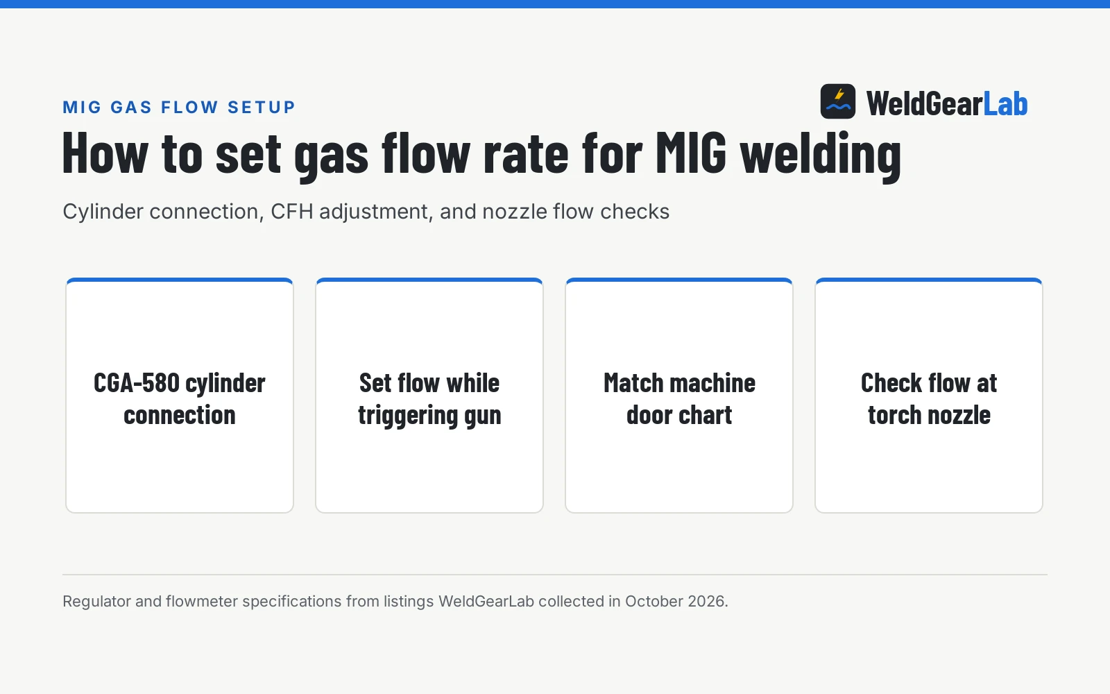
Learning how to set gas flow rate for mig welding comes down to a clear sequence: connect your regulator securely to the cylinder, adjust the valve while triggering the gun so gas is actively flowing, and set the flow rate recommended for your setup. Setting the rate while gas flows ensures the regulator delivers proper shielding without falling short during an arc. Too little shielding gas lets air contaminate the puddle and cause porosity, while excessive flow creates turbulence that pulls air into the arc zone. This guide explains how to dial in flow and verify delivery at the nozzle.
As an Amazon Associate I earn from qualifying purchases. This guide links to our product roundups, where WeldGearLab earns a commission when you buy through links, at no extra cost to you. Read our affiliate disclosure.
How to set gas flow rate for mig welding
Shielding gas protects molten weld metal from oxygen, nitrogen, and atmospheric moisture. In solid-wire MIG welding, gas travels from a high-pressure cylinder through a regulator and hose, enters the machine solenoid, and exits through the torch gas nozzle around the contact tip. The volume exiting the torch is measured in cubic feet per hour, abbreviated as CFH. Setting the correct flow rate maintains a smooth blanket of gas over the weld puddle without drawing in outside air.
Most equipment manuals and door charts recommend starting settings based on nozzle diameter and joint type. Regulators provide calibrated measurement ranges: ARCCAPTAIN specifies an output range of 0-30 CFH for argon and 0-20 CFH for carbon dioxide on its dual gauge model, while flow tubes from YESWELDER, BOWELD, and Bestarc measure from 0 to 60 CFH. Always start with your manual’s recommendation, then adjust for puddle coverage.
Side by side
| Flow tube regulator | Dual dial gauge regulator | Torch nozzle flowmeter | |
|---|---|---|---|
| Measurement location | Cylinder outlet | Cylinder outlet | Torch gas nozzle |
| Flow indication mechanism | Vertical tube with floating ball | Dial face reading backpressure | Vertical tube with floating ball |
| Dynamic gas flow reading | Indicates flow rate during purge | Indicates flow rate during purge | Measures output exiting nozzle |
| Supply pressure measurement | High-pressure dial gauge on inlet | High-pressure dial gauge on inlet | Not stated (no pressure dial) |
| Typical measurement scale | 0 to 60 CFH (up to 70 CFH on SPARC) | 0-30 CFH argon, 0-20 CFH CO2 (ARCCAPTAIN) | 0 – 25 litres per minute (Sxstar) |
| Connection type | CGA-580 cylinder connection | CGA-580 (or CGA-320 with adapter) | Flexible rubber nozzle cone |
| Response to torch line restriction | Ball drops if hose kinks or line blocks | Dial still indicates set flow | Directly measures flow drop at nozzle |
| Reference brand examples | YESWELDER, SPARC, BOWELD, Bestarc | SÜA, ARCCAPTAIN, MEANLIN MEASURE | Sxstar |
Choosing between a floating ball flowmeter, a dual dial gauge regulator, and a handheld nozzle flowmeter depends on where you monitor gas delivery. A cylinder flowmeter with a vertical sight tube measures dynamic gas flow directly: as shielding gas flows, a precision ball rises to indicate flow rate. Models from YESWELDER, BOWELD, and Bestarc feature tubes scaled from 0 to 60 CFH, while SPARC provides an expanded scale from 0-65CFH for argon and 0-70CFH for argon and carbon dioxide blends. If a hose kinks or the nozzle clogs, the ball drops immediately, warning you that delivery has stalled.
Dual gauge regulators, such as units from SÜA and ARCCAPTAIN, use two round dials. One dial shows cylinder pressure, reading on scales such as 0–4000 PSI (with SÜA rated for 3,000 psig inlet, BOWELD reading 0-3500 PSI, and MEANLIN MEASURE reaching 0-4500 PSI). The second dial reads backpressure across an internal orifice. If a nozzle clogs, the dial continues showing set flow even when delivery drops. To verify flow directly at the torch, a nozzle gauge like the Sxstar unit measures actual output from 0 – 25 litres per minute.
Connecting the regulator and checking for leaks
Before setting gas flow, mount the regulator cleanly and leak-free on the shielding gas bottle:
- Clear the cylinder valve. Stand behind the cylinder outlet, point the valve opening away from people, and crack it open for a fraction of a second to blow out dust from the threads, then close it firmly.
- Mount the regulator. Cylinders for argon and argon blends use CGA-580 connections, while pure carbon dioxide bottles use CGA-320 valves. Thread the matching inlet nut into the cylinder valve by hand to prevent cross-threading, then tighten securely with an open-end wrench. Do not use thread tape on CGA-580 brass-to-brass mechanical seats.
- Attach the gas hose. Connect the shielding gas hose to the regulator outlet. Standard connections include female 9/16″ x 18 nuts, male 5/8″ x 18 fittings, or 1/4″ hose barbs with clamps, as found on YESWELDER, BOWELD, and Bestarc models. SPARC includes a 5/8″ UNF-18RH nut and a barb for 1/4″ and 5/16″ hose. SÜA provides a 10 ft hose with 5/8-18 fittings, YESWELDER and Bestarc supply an 8.2ft hose, and MEANLIN MEASURE includes a 6.5 Feet hose. Connect the other end to your machine gas inlet.
- Pressurize and check for leaks. Close the regulator valve: back out a dual-gauge T-handle counterclockwise until loose, or turn a flowmeter needle valve gently clockwise until seated. Stand to the side of the gauge dial, slowly open the cylinder valve until the inlet gauge registers bottle pressure, then open it fully on double-seating inert valves. Apply soapy leak detection solution to the cylinder stem, CGA-580 nut, and hose connections. If bubbles appear, close the bottle, vent pressure, and tighten the joint.
Adjusting your MIG CFH setting while purging
A frequent mistake is adjusting the regulator while the machine is idle. With the gun trigger released, the gas solenoid remains closed, leaving flowmeter balls resting at zero and line pressure trapped.
To set your active mig cfh setting correctly, gas must flow through the torch while you adjust the valve. Release the wire drive roll tension arm inside the cabinet so wire does not feed into the cable. Many machines include a gas purge button that opens the solenoid without feeding wire. If your machine lacks a purge switch, disengaging drive tension lets you pull the trigger, but keep the torch pointed away from metal because the welding circuit remains live.
With the trigger depressed and gas flowing, adjust the valve: turn the T-handle clockwise on a dual-gauge regulator, or turn the needle valve counterclockwise on a flowmeter tube. On a sight-tube meter like YESWELDER or SPARC, read the floating ball against the stamped CFH scale (checking markings, as meters read at the ball center while nozzle gauges like Sxstar read from the top). On a dial gauge like SÜA or ARCCAPTAIN, turn the T-handle until the needle aligns with the desired number. Release the trigger, re-engage wire drive tension, and close the cabinet door.
Checking actual flow at the torch nozzle
Setting the CFH rate at the cylinder confirms what leaves the regulator, but hose leaks, loose solenoid fittings, or damaged torch O-rings can bleed off shielding gas before it reaches the contact tip.
To verify delivery at the puddle, welders use a handheld nozzle flow meter. Sxstar manufactures a handheld flow meter scaled from 0 – 25 litres per minute in one litre graduations designed specifically to check gas flow at the gun nozzle. Press the rubber base firmly over the torch nozzle, hold the tube vertically, and pull the trigger with wire feed disengaged. Gas pushes a small ball up the transparent tube, providing a direct measurement of torch output.
If the regulator shows an adequate setting but the nozzle gauge reads low, inspect the hose fittings, verify that the torch back end is fully seated in the drive housing, and check internal rubber seals for damage.
Managing drafts, spatter, and porosity
Getting clean welds requires balancing shielding flow against shop conditions. When setting up a wire feed machine, such as entry-level models covered in our best MIG welder under 500 guide, environmental factors and torch care directly affect weld quality:
- Shielding gas selection. Mild steel is commonly welded using an argon and carbon dioxide mixed gas for a stable arc and moderate spatter. Pure carbon dioxide provides deeper penetration but increases spatter. ARCCAPTAIN lists separate scales for argon and carbon dioxide because gas densities affect flow rates through a fixed opening.
- Drafts and outdoor air. Even a gentle breeze can blow away the gas blanket. Cranking flow higher causes turbulent flow at the nozzle, pulling oxygen and nitrogen into the pool. Instead of over-adjusting the regulator, set up solid wind screens around your welding area.
- Torch nozzle cleanliness. Spatter accumulating inside the nozzle disrupts the shielding envelope. Clean the nozzle frequently with welding pliers. If gas coverage remains uneven or you see pinholes, consult our guide on what causes porosity in MIG welds to diagnose gas loss and contamination.
Gas cylinder and ventilation safety. Always secure high-pressure gas cylinders upright with a safety chain to a welding cart or wall bracket. Stand with the cylinder between you and the regulator when opening the valve so you do not face the gauge lens. Maintain shop ventilation, keep your head out of the fume plume, and review OSHA safety standards for compressed gas handling.
Frequently Asked Questions
Should I set MIG gas flow with the trigger pulled?
Yes, always adjust the regulator while shielding gas is actively flowing through the gun. Triggering flow via a purge button ensures you set active operating flow rather than trapped static line pressure.
What happens if MIG gas flow is set too high?
Setting flow too high creates turbulent flow at the nozzle rather than a smooth protective blanket. This turbulence pulls room air into the shielding stream, introducing oxygen and nitrogen that cause porosity and heavy spatter.
What causes gas flow to drop while welding?
A drop in flow is usually caused by spatter buildup inside the nozzle, a kinked gas hose, or an emptying cylinder. Check your cylinder pressure gauge regularly and clean the nozzle with welding pliers to keep gas ports clear.
Is a floating ball flowmeter better than a dual gauge regulator?
A floating ball flowmeter tube directly indicates active flow and immediately drops if a hose kinks. Dual gauge regulators estimate flow from backpressure and continue indicating set flow even if a clogged nozzle restricts delivery.
Can I use pure carbon dioxide with a standard argon regulator?
Pure carbon dioxide cylinders use a CGA-320 valve connection, while argon and mixed gas cylinders use CGA-580. As SÜA notes on its regulator, connecting to a carbon dioxide bottle requires a dedicated regulator or a brass adapter.
Related: gas regulator for welder guide, why a MIG welder spatters, how to choose a MIG welder, and the MIG welders hub.
About the author
WeldGearLab Editorial is the editorial team behind WeldGearLab. We research product listings, specifications, safety listings and warranty terms, score every pick with the published Gear Score method, and correct errors when readers report them. We do not run our own shop trials; see How We Pick for exactly how picks are made.